Recently, I was sorting out a report on the automotive lighting industry chain. In the process of searching for information, I saw an environmental impact assessment announcement, which introduced the production process of automotive lighting in detail. I would like to share it with you. You are welcome to join the group to discuss and share more technical information.

1. Car lamp production process
Introduction to the main production process:
Add plastic particles or BMC raw materials to the barrel of the injection molding machine, inject them into the corresponding mold for molding, remove the molded product, and trim it according to the different needs of the product, then undergo PC hardening or BMC primer or vacuum aluminum plating, or BMC After primer coating and vacuum aluminum plating, the aluminum-plated reflector is obtained. Finally, each component is assembled with purchased parts. Except for the car taillight assembly process, which requires welding, other car lights are bonded with sealant during the assembly process. The assembly is completed. After passing the inspection, the products are packaged and sent to the warehouse.
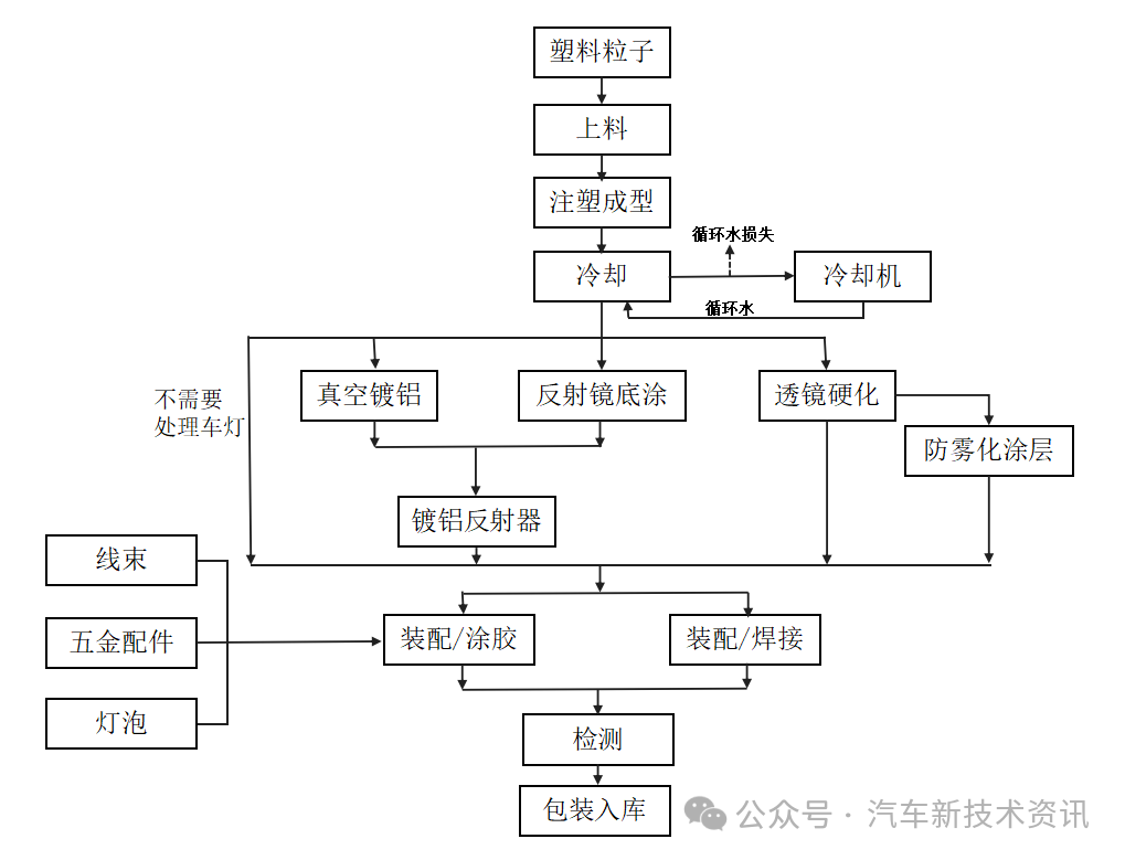
Car lamp production process flow chart
Introduction to key processes:
1) BMC injection molding
Mainly used in the manufacture of automobile headlights and fog light reflectors
The raw material is injection molded thermosetting material, namely BMC material. The BMC material composition mainly contains 60-70% carbonate, 10-20% glass fiber and 10-15% unsaturated polyester.
A standard injection molding machine is used, as follows: Bulk BMC material is injection molded at a temperature of 20°-50°C. When the temperature reaches 150-170°C, the BMC material obtains a cross-linked structure and is injected into the corresponding mold.
After being cooled by indirect cooling water circulation, it is formed. The injection mold is automatically opened and demoulded. After manual trimming to remove excess plastic, the finished product is the finished product after passing the inspection. The leftover materials produced by manual trimming and unqualified products produced by inspection are crushed by the crusher. Supplier recycling.
2) Plastic particle injection molding
The plastic particles are introduced into the hopper of the integrated injection molding machine, heated to 220°C-300°C by electricity to melt the plastic particles, injected into the corresponding mold, cooled by indirect cooling water circulation, and then molded. The molded product is removed from the mold and trimmed manually. Excess plastic is removed and the finished product is ready after passing the inspection. The scraps produced by manual trimming and the unqualified products produced by the inspection are crushed by the crusher and recycled by the supplier.
3) Vacuum aluminum plating
Aluminize the surface of the condenser circle and reflector in a vacuum aluminum plating machine. Wrap the aluminum wire around the tungsten wire electrode rod → install the plastic parts to be coated on the fixture and send them into the vacuum chamber of the coating machine → close the door → apply rough vacuum to 3.0×10⁻²Pa and ion clean the surface of the plastic parts → apply high vacuum to 0.1~4.0×10⁻³Pa, preheat the tungsten wire evaporation source → aluminum evaporation, close the high-pressure valve → plasma overlap the outer silicon oxide protective film → atmospheric backfill → open the door and take out the coated plastic parts.
4) Reflector primer
Process introduction: Mainly spraying BMC injection molded reflectors
① Grinding: Grind the injection molded parts of the reflector to remove burrs.
②Cleaning process: The cleaning process is a process of spray cleaning the debris left behind after deburring the reflector with water containing cleaning agent. The cleaning process is detailed in the figure.
The cleaning process is as follows, divided into four cleaning tanks. The first cleaning tank is cleaned with detergent. The cleaning agent type is detergent. The cleaning agent removes impurities on the surface of the workpiece. The second, third and fourth cleaning tanks are respectively Rinse with water filtered through the filter membrane to remove static electricity and increase surface activity.
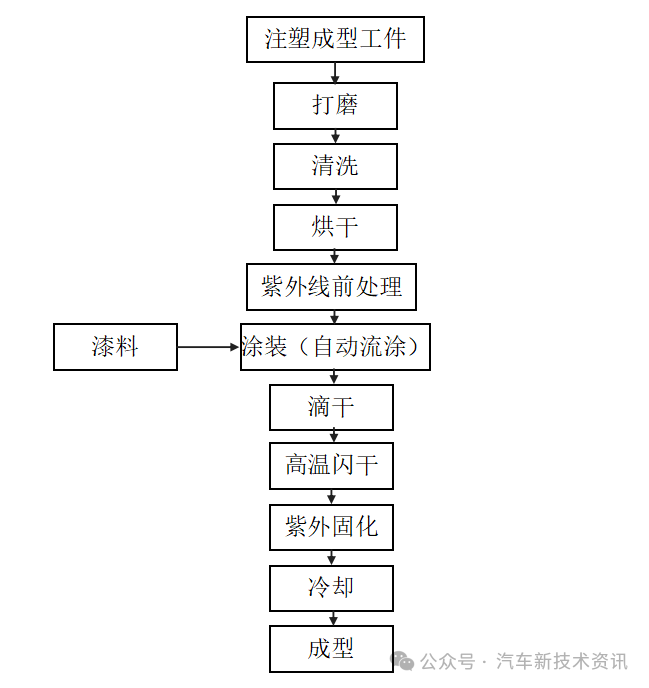
Reflector primer production process flow chart
Project cleaning process flow chart
③Drying process: After the workpiece passes the cleaning process, it enters the drying system. The drying system uses a burner device to burn natural gas to form hot air that passes through the coil and is discharged through a 15-meter-high chimney. At the same time, a fan is set up in the drying furnace. The fan circulates the air through the coil, and the hot air cleans the The final workpiece is dried at a drying temperature of about 120°C.
④Flow coating process: After drying, the workpiece enters the flow coating process with the conveyor belt.
Coating (automatic flow coating system): Automatic flow coating consists of a flow coating tank, a paint stirrer, an electronic control and a pump tube system. A sewage pump is used for flow coating circulation, and an explosion-proof motor is used for mixing, which is safe, reliable, no leakage, efficient and non-clogging. It has the characteristics of uniform coating mixing, fast flow coating and uniform coating thickness. Use a flow coating tank equipped with a filter to place the workpiece to be poured on the net. The paint is fed into the high tank by a pump. The coating must be uniform up and down. The excess paint dripping on the surface of the workpiece can still flow into the paint tank through the filter. in the tank, and then use the pump to press it back into the high-level tank from the tank to continue recycling.
High-temperature flash-drying process: The indoor temperature of the flash-drying section is 80°C, and the heating time is 2-3 minutes. The heat is provided by the hot steam of the boiler and is indirect heating.
Ultraviolet curing: The workpiece enters the ultraviolet area, and the surface of the coating film is irradiated with ultraviolet light with an illumination of 3300-5500mj/cm2 for 3-10 minutes to solidify the coating into a film.
⑤Cooling: Use cooling water to lower the temperature of the filtered air for cooling, and cool the high-temperature solidified workpiece to 25-30°C.
⑥Unloading: Manual unloading. The temperature and humidity in all processes are controlled, and each process must meet the requirements of air purification. The air comes from outdoor air filtered by filters.
5) Lens hardening
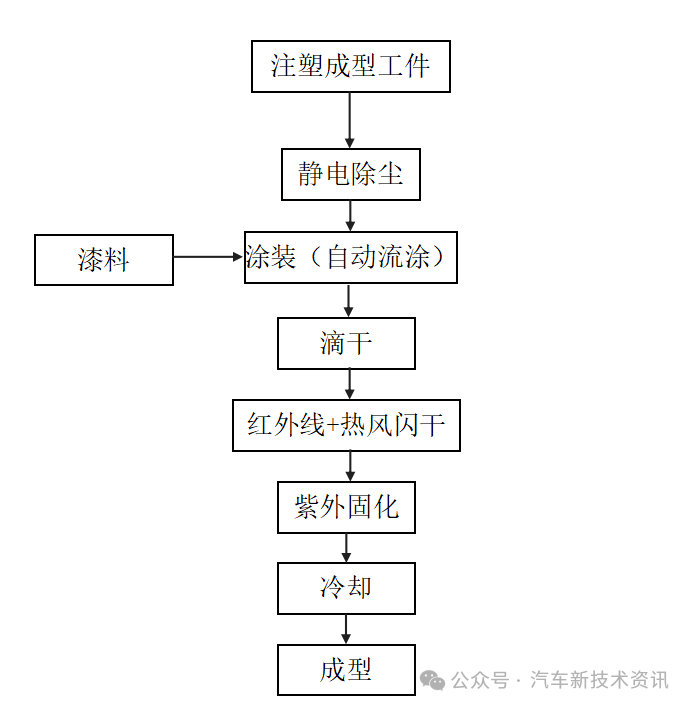
Lens hardening production process flow chart
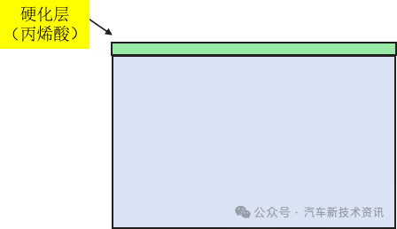
Process introduction: Lens hardening is part of the manufacturing process of automobile headlights. It mainly sprays the outside of the headlights. The polycarbonate lens must be protected from scratches and weather factors. Therefore, the surface is covered with a layer of paint to harden and protect the lens. As shown below:
First, the workpiece is dusted through the static-free dust blowing and exhausting workbench, and then enters the automatic flow coating process.
Coating (automatic flow coating system): Automatic flow coating consists of a flow coating tank, a paint stirrer, an electronic control and a pump tube system. A sewage pump is used for flow coating circulation, and an explosion-proof motor is used for mixing, which is safe, reliable, no leakage, efficient and non-clogging. It has the characteristics of uniform coating mixing, fast flow coating and uniform coating thickness. Use a flow coating tank equipped with a filter to place the workpiece to be poured on the net. The paint is fed into the high tank by a pump. The coating must be uniform up and down. The excess paint dripping on the surface of the workpiece can still flow into the paint tank through the filter. in the tank, and then use the pump to press it back into the high-level tank from the tank to continue recycling.
Infrared + hot air flash-drying process: the first stage of infrared + hot air preheating and flash-drying stage, infrared uses far-infrared heating with a wavelength of 2.4-2.7μm, and hot air is the heat provided by the hot steam of the boiler, which is indirect heating. The indoor temperature of the flash-drying section is 65-80°C, and the heating time is 2-3 minutes.
Ultraviolet curing: The second stage is the ultraviolet curing stage. The surface of the coating film is irradiated with ultraviolet rays with an illumination intensity of 3300-5500mj/cm2 for 3-10 minutes to solidify the coating into a film.
Cooling: Use cooling water to lower the temperature of the filtered air for cooling, and cool the high-temperature solidified workpiece to 25-30°C.
Unloading: Manual unloading. The temperature and humidity in all processes are controlled, and each process must meet the requirements of air purification. The air comes from outdoor air filtered by filters.
6) Anti-fog coating
①Automatic flow coating
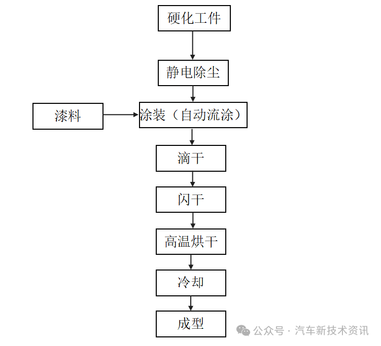
Automatic flow coating anti-fog coating production process flow chart
Process introduction: First remove dust from the workpiece through the static-removing dust blowing and exhausting workbench, and then enter the automatic flow coating process.
Coating (automatic flow coating system): Automatic flow coating consists of a flow coating tank, a paint stirrer, an electronic control and a pump tube system. A sewage pump is used for flow coating circulation, and an explosion-proof motor is used for mixing, which is safe, reliable, no leakage, efficient and non-clogging. It has the characteristics of uniform coating mixing, fast flow coating and uniform coating thickness. The flow coating tank equipped with a filter is used to place the workpiece to be poured on the net. The paint is input into the high tank by a pump. It must be evenly poured up and down. The excess paint can still flow into the paint tank after passing through the filter. The pump presses back from the tank to the high level tank for continued circulation.
Flash drying: at 50-55°C, preheat for 5 minutes, using electric heating.
High temperature curing: Heating at 120-130°C for 25-35 minutes to solidify the paint into a film, using electric heating.
Cooling: Use cooling water to lower the temperature of the filtered air for cooling, and cool the high-temperature solidified workpiece to 25-30°C.
Unloading: Manual unloading.
The temperature and humidity in all processes are controlled, and each process must meet the requirements of air purification. The air comes from outdoor air filtered through filters.
②Automatic spraying
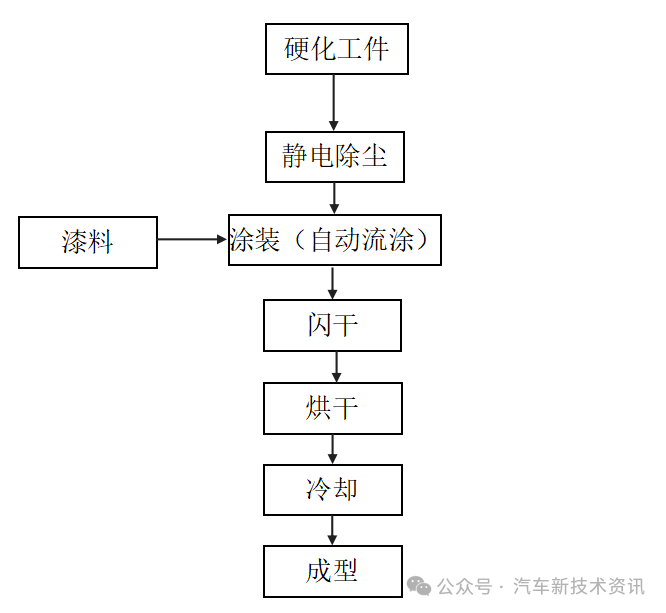
Automatic spraying anti-fog coating production process flow chart
Process introduction: First remove dust from the workpiece through the static-removing dust blowing and exhausting workbench, and then enter the automatic spraying process:
Painting (ABB automatic spraying system): Automatic spraying consists of a spraying robot, paint stirrer, electronic control and pump pipe system. The spray robot uses air pressure to disperse the paint into uniform and fine mist droplets, and then applies it to the surface of the workpiece.
Flash drying: at 50-55°C, preheat for 5 minutes, using electric heating.
High temperature curing: Heating at 120-130°C for 25-35 minutes to solidify the paint into a film, using electric heating.
Cooling: Use cooling water to lower the temperature of the filtered air for cooling, and cool the high-temperature solidified workpiece to 25-30°C.
Unloading: Manual unloading.
The temperature and humidity in all processes are controlled, and each process must meet the requirements of air purification. The air comes from outdoor air filtered by filters.
2. LED module production process
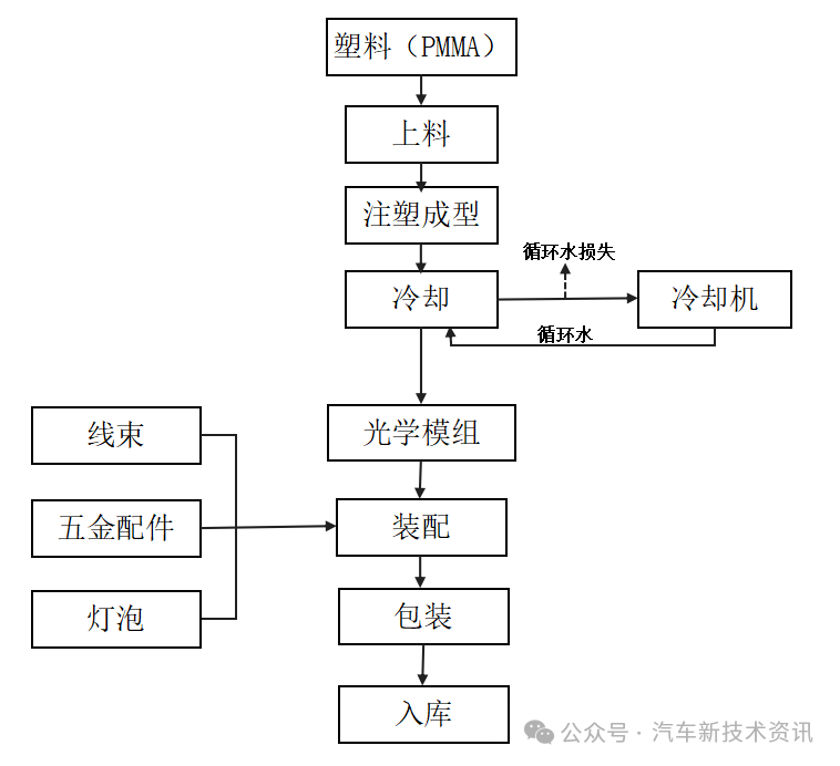
LED module production process flow chart
Introduction to the main production process:
Loading: The raw materials for the project production are mainly PMMA plastic particles that are added into the feeding barrel through manual feeding. The temperature that needs to be controlled during the molding process is the barrel temperature of 55°C.
Injection molding: After loading, the plastic particles are transported to the injection molding machine through an automatic conveying system, and plastic products of various shapes are made using plastic molding molds. The plasticizing temperature is 220-240°C. The mold filling time is generally about 10-15 seconds.
Cooling: The injection molded plastic product should be cooled and shaped immediately after leaving the injection molding machine head. The cooling method uses circulating cooling water. The cooling time is generally between 30 and 120 seconds.
Assembly: The formed optical module (LED lens) is assembled with the purchased wiring harness, lamps, and hardware. The finished product is packaged after inspection.
— — end — —
The above content comes from the Environmental Impact Assessment Announcement of Magneti Marelli Auto Lighting Project

Event Recommendation 1: The 5th Intelligent Car Lighting Innovation Technology and Supply Chain Forum (May 16, Chongqing)

|
|
|
|
|
|
|
|
|
|
|
|
|
|
|
|
|
|
|
|
|
|
|
|
|
|
|
|
|
|
|
|
|
|
|
|
|
|
|
|
|
|
|
|
|
|
|
|
|
|
|
|
|
|
|
|
|
|
|
|
|
|
|
|
|
|
|
|
|
|
|
|
|
|
|
|
|
|
|
|
|
|
|
|
|
|
|
|
|
|
|
|
|
|
|
|

The original article was originally published on WeChat public account (automotive new technology information):Introduction to automobile lamp production process

