什么是LBS
Persistence effect of human vision
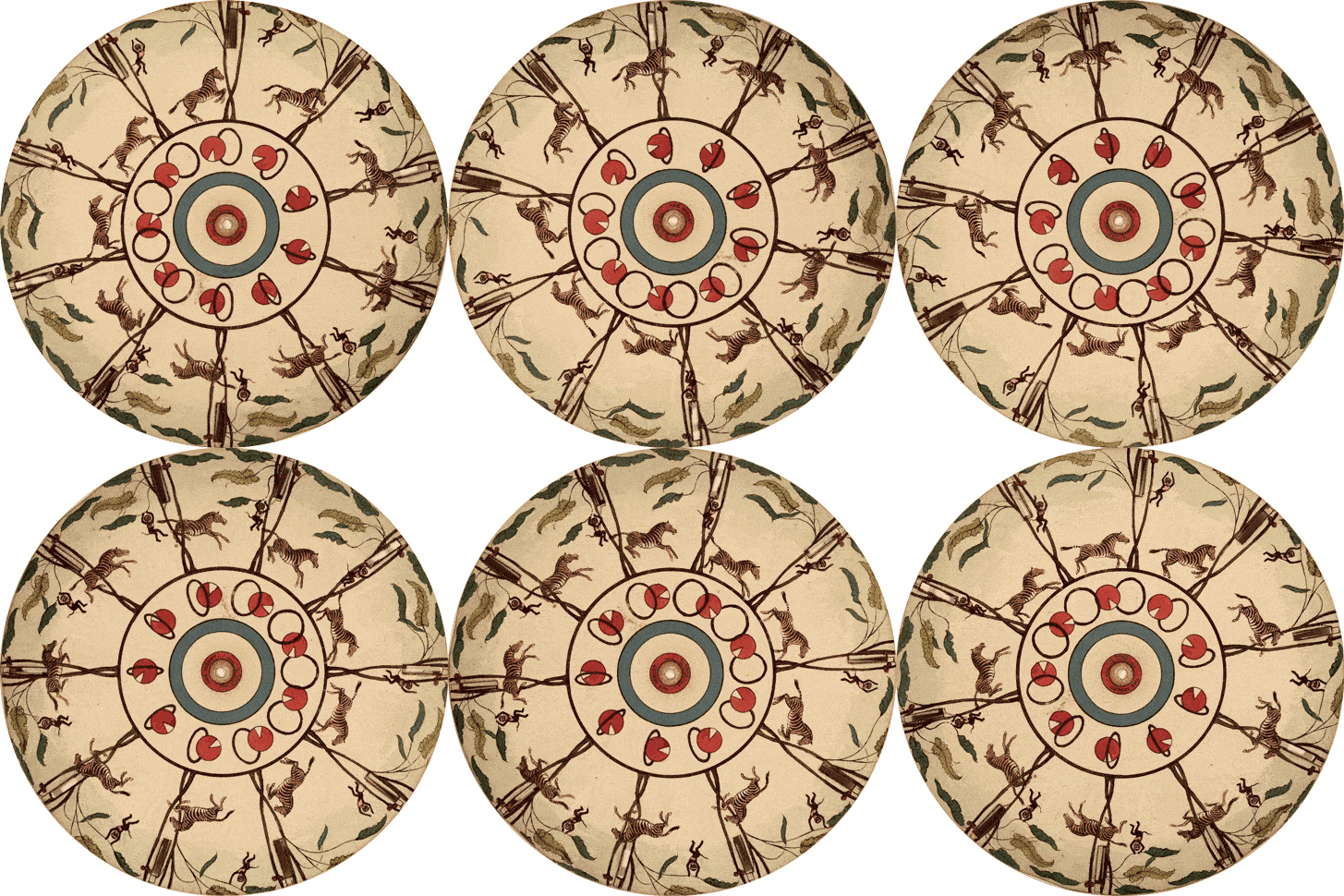 图(1).走马灯示例图
LBS imaging mechanism
A typical LBS system usually consists of RGB laser, MEMS galvanometer and control system.[1]. Among them, the MEMS galvanometer is the most critical. It is a tiny driveable reflector based on MEMS (Micro-Electro-Mechanical System) technology.[3]. During operation, the MEMS galvanometer can tilt the mirror surface according to different driving methods (common electrostatic driving and piezoelectric driving) to control the beam deflection (Figure (2))[3]。
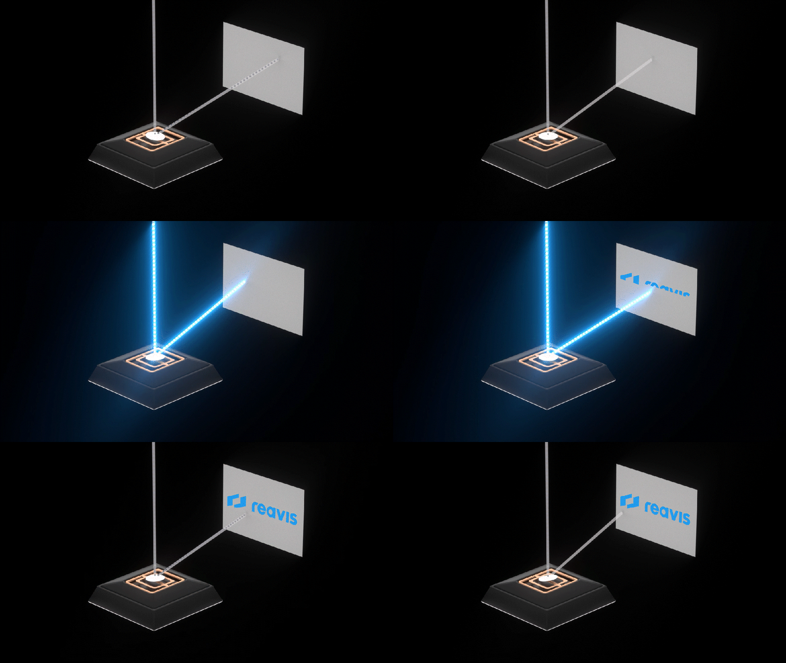 图(2).MEMS振镜工作原理
During LBS operation, The RGB laser first produces three types of laser beams: red, green, and blue. The laser beam is coupled to the surface of the MEMS galvanometer through an optical system. Secondly, the electronic control system will calculate and control the deflection angle and velocity of the MEMS galvanometer based on the information of the image to be displayed, deflecting the laser beam to a specific position where it forms a pixel point[1]。
As shown in Figure (3), after completing the scanning deflection of one pixel, The MEMS galvanometer will repeat the previous steps for the remaining pixels until a complete frame of the image is drawn. Although only one independent pixel appears on the imaging surface each time, combined with the human eye persistence phenomenon mentioned earlier, the human eye and brain can fully perceive each frame of the image from the point to the surface[1]。
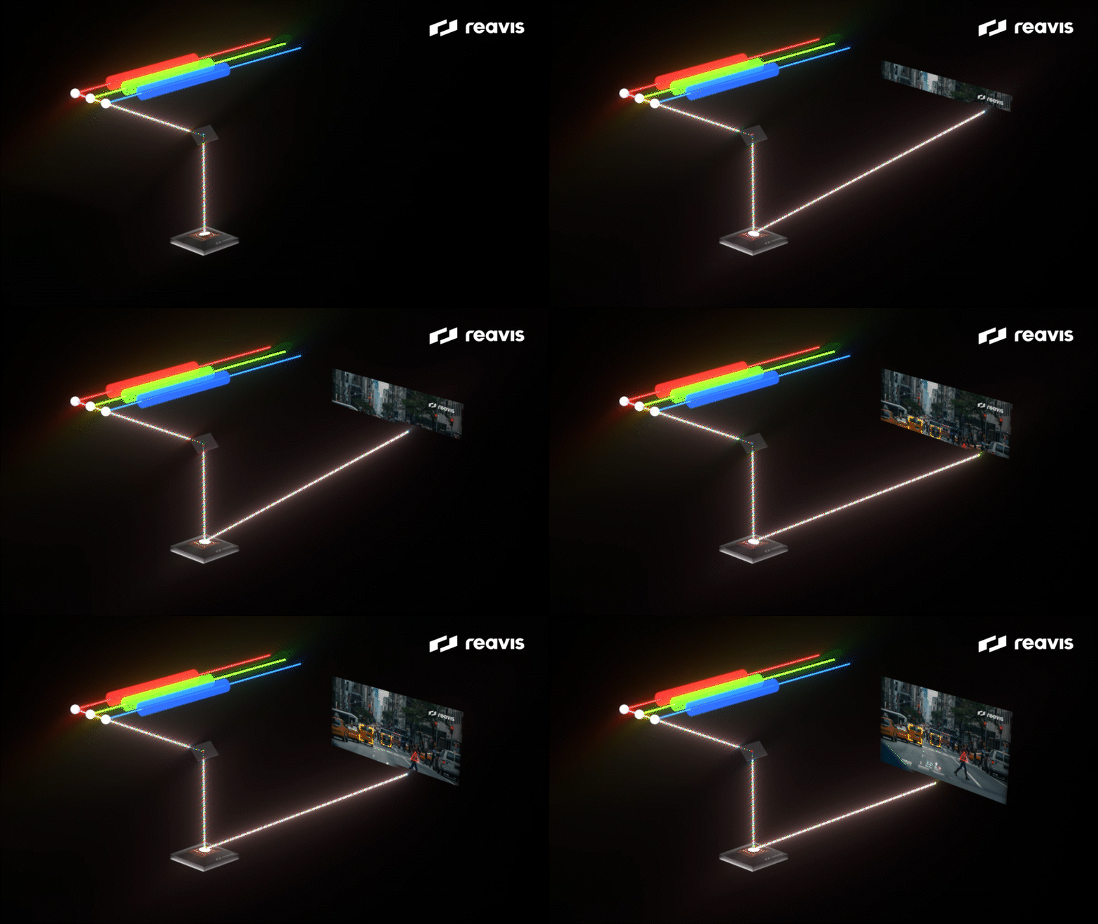 图(3).LBS成像原理
Advantages of LBS
Small size and flexible usage scenarios
Due to its unique design and structure, LBS has the advantage of compact size. Traditional display technologies (such as DLP) often require the use of multiple lenses and optical components to focus imaging[4]LBS only requires RGB laser and one or more small-sized micro MEMS mirrors for scanning and imaging. Therefore, compared to other imaging systems, LBS does not require complex optical systems to achieve imaging, thus, LBS has significant advantages in terms of volume (Figure (4)). Meanwhile, as LBS is a scanning imaging system, there is no fixed imaging focal length, which allows for clear projection at different projection distances and surfaces, thus providing higher flexibility in usage scenarios[4]。
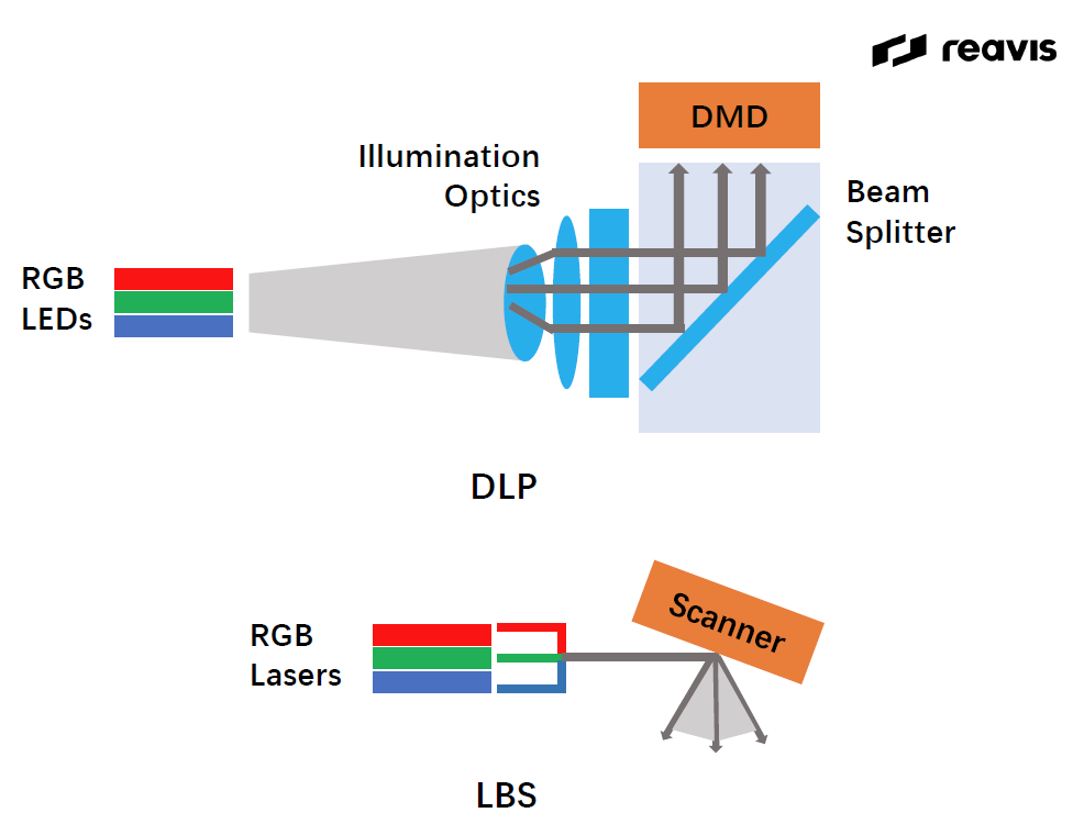 图(4)Comparison of volume construction between LBS and DLP
Low power consumption
Compared to traditional LCD display technology, LBS has lower power consumption. Looking at it in detail, compared to LCD technology that requires the entire panel for illumination, LBS uses MEMS mirrors to precisely control the laser scanning path, consuming only the energy required on the actual display pixels; Meanwhile, the backlight is usually one of the largest energy consumption sources in LCD display devices, and LBS can image without the need for additional backlight, which can significantly reduce power consumption[5]。
High contrast
In addition, The laser source of LBS also has the characteristic of high monochromaticity, which concentrates the projection energy during projection, producing brighter, clearer, and fuller colors[6]。
Traditional DLP and LCD cannot control each micro lens individually with a backlight during imaging, and can only illuminate the entire array area at once[7]; LBS uses a laser light source, with the beam moving point by point, illuminating only a small area at a time to form the desired image. By adjusting the scanning path and intensity of the laser beam, the brightness of each point in LBS imaging can be controlled. Therefore, LBS achieves a greater brightness difference between the bright and dark parts, thereby enhancing the contrast of the image and giving it better visual expression (Figure (5))[6]。
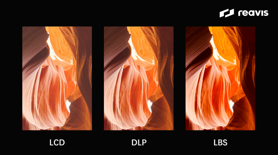 图(5)LBS LCD and DLP display effects
Better color performance
LBLBS can cover a wider color gamut. The core light source is a laser light source, and one of the characteristics of a laser light source is that it can output a pure narrowband spectrum, which has better monochromaticity, so the colors produced have higher color purity. Therefore, in the laser light source of LBS, the chromaticity triangle area composed of red, green, and blue is larger, that is, the color gamut is larger(图(6)). In other words, display devices using LBS can display a greater number of colors, bringing richer colors and more natural and delicate color transitions[7]。
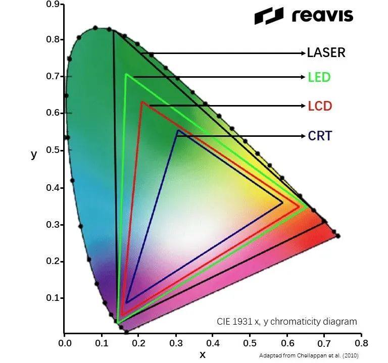 图(6).Laser light source (LASER) Possible color gamut for LED, LCD, and CRT displays
Disadvantages of LBS
Although LBS has smaller size and power consumption, better imaging contrast and color performance, it also has disadvantages in imaging and application due to its laser and imaging characteristics.
Speckle pattern
The laser source produces highly coherent light. When the laser is incident on a rough surface and scatters, electromagnetic waves interfere with each other in space to form granular patterns with randomly distributed intensity and phase. The irregular pattern captured by the human eye is called laser speckle. The laser speckle image will bring bright and dark spots to the entire screen display (Figure (7) (A)). Compared with the normal imaging effect (Figure (7) (B)), it will have what we usually call a "frosted glass" texture, which affects the imaging clarity of the image[8]。
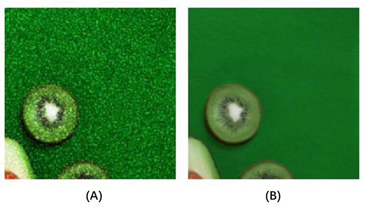 图(7)Comparison of speckle effects
In order to reduce the negative impact of speckle reduction, The LBS optical machine requires additional methods to reduce the coherence of the output light of the laser source or to superimpose speckle patterns through time-division multiplexing. However, the design of speckle elimination methods is complex, requires high equipment accuracy, and may affect the clarity and brightness of the system image. Therefore, there is currently no widely used speckle elimination solution[9]。
distortion
Due to the scanning method and optical characteristics, LBS imaging may have geometric or color distortions in the image. During the scanning process, the speed of MEMS galvanometer changes, usually slowing down at the scanning edge. At the same time, when scanning areas far from the center, the increase in scanning angle may cause the image edge to bend or stretch, resulting in geometric distortion. In addition, lasers with different colors have different wavelengths and may focus at different positions, resulting in color separation or blurring at the edges. The non-linear speed of scanning can also cause inconsistent brightness in different parts of the image, which is known as color distortion[10]。
Difficulty in achieving high resolution
LBS utilizes the persistence characteristics of human vision for imaging, and the image resolution is closely related to the scanning rate of MEMS scanning mirrors. For LBS, all pixels need to be refreshed at least 20 times within 1 second to ensure stable image display. To achieve the same HD1080 display effect as current display devices (with a resolution of 1920 * 1080), The MEMS resonant frequency will need to be from 18kHz in VGA format[1]Raised to 40.5kHz[11]. MEMS scanning mirrors are unable to maintain such high scanning frequencies, which limits the image resolution of LBS.
Color instability
LBS uses lasers, RGB lasers are sensitive to temperature, and Figure (8) shows the characteristics of RGB laser output power as a function of temperature. It can be seen that the output power of blue laser is relatively stable at different temperatures, but red and green lasers exhibit significant temperature drift when the ambient temperature exceeds 40 ℃. In this case, the wavelength emitted by the laser will drift, the mode will be unstable, and even unable to work properly[12]。
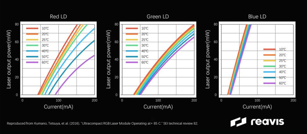 图(8). RGB激光输出功率随温度变化示意图
Current Development Status of LBS
Existing applications
LBS has multiple applications in different fields. In the fields of AR and VR, The LBS system can achieve a compact and lightweight design, providing users with an immersive visual experience; In the field of 3D scanning and imaging, LBS can generate detailed 3D models of objects or environments, which can be used for industrial design, cultural heritage protection, etc; In terms of LiDAR perception, LBS is used to scan and measure distances and create detailed 3D maps of the surrounding environment; In addition, due to higher imaging contrast and better color performance, LBS can also be applied in cinemas and large outdoor displays[13]。
In car applications
In the field of vehicle transportation, LBS optical technology can be applied to car mounted HUD (Head Up Display) systems, and broaden the HUD technology roadmap from two aspects: volume and reducing the risk of sunlight backflow. Due to its small size, theoretically LBS can effectively solve the problem of PGU volume proportion in HUD and achieve a larger field of view (FOV) at the same volume. Meanwhile, as LBS is a projection technology that requires diffusion film for primary imaging, this means that the high-energy density solar radiation gathered by the external HUD optical system will not be loaded onto the optical machine body, thereby reducing the risk of sunlight backflow[14]. However, there are still many issues that need to be addressed in the onboard LBS technology, such as cost, temperature drift, vibration, speckle, and other characteristic issues, as well as comprehensive certification of vehicle reliability. Therefore, there is currently no relevant plan for mass production implementation. Therefore, for LBS, mass production on the vehicle is a challenge while maintaining costs without adding too many additional measures.
In summary, The structural composition and laser characteristics of LBS bring it different advantages in imaging and other aspects, but also lead to its high difficulty and high requirements in HUD applications. Understanding the detailed principles of LBS helps to better evaluate and optimize its impact on imaging quality and practical scene applications.
#参考来源:
[1]Petrak, Oleg, et al. (2021). "Laser beam scanning based AR-display applying resonant 2D MEMS mirrors." Optical Architectures for Displays and Sensing in Augmented, Virtual, and Mixed Reality (AR, VR, MR) II. Vol. 11765.
[2]Anderson J, Anderson B. (1993). "The myth of persistence of vision revisited." Journal of Film and Video, 3-12.
[3]Wang, Dingkang, Connor Watkins, and Huikai Xie. (2020). "MEMS mirrors for LiDAR: A review." Micromachines 11(5): 456.
[4]LI Zhao, YUAN Weizheng, WU Meng, et al. (2011). "Micro scanning mirrors with laser diode for pattern generation." Acta Photonica Sinica, 40(11): 1625-1629.
[5]Hofmann, Ulrich, Joachim Janes, and Hans-Joachim Quenzer. (2012). "High-Q MEMS resonators for laser beam scanning displays." Micromachines 3.2: 509-528.[6]Niesten, Maarten, Randy Sprague, and Josh Miller. (2008). "Scanning laser beam displays." Photonics in Multimedia II. Vol. 7001.
[7]Tsai, Pei-Shan, et al. (2009). "Image enhancement for backlight-scaled TFT-LCD displays." IEEE Transactions on Circuits and Systems for Video Technology 19.4: 574-583.
[8]Briers, David, et al. (2013). "Laser speckle contrast imaging: theoretical and practical limitations." Journal of biomedical optics 18.6: 066018-066018.
[9]Akram, M. Nadeem, and Xuyuan Chen. (2016). "Speckle reduction methods in laser-based picture projectors." Optical Review 23.1: 108-120.
[10]Dai, K., and Louie Shaw. (2002). "Distortion minimization of laser‐processed components through control of laser scanning patterns." Rapid Prototyping Journal 8.5: 270-276.
[11]Okamoto, Yuki, et al. (2018). "High-uniformity centimeter-wide Si etching method for MEMS devices with large opening elements." Japanese Journal of Applied Physics 57.4S: 04FC03.
[12]Kumano, Tetsuya, et al. (2016). "Ultracompact RGB Laser Module Operating at+ 85 C." SEI technical review 82.
[13]Merlemis, Nikolaos, Anastasios L. Kesidis, etc. (2020). "Measurement of laser beam spatial profile by laser scanning." European Journal of Physics 42.1: 015304.
[14]McDonald, T. Gus, and Pierre Mermillod. (2023). "Speckle mitigation techniques for laser point scanned displays in head-up display applications." Advances in Display Technologies XIII. Vol. 12443.
The original text originates from WeChat official account (ReaVis):Principle of optical mechanical LBS

长按识别二维码,加入群聊
 Welcome to join us.艾邦HUD通讯录,目前有2500人,包含各大HUD厂商以及主机厂负责人均已经加入,可以通过点击下方关键词查看
OEM Autonomous Driving (V2X) HUD厂商 HUD初创 TFT影像源 DLP光机 MEMSLSP chip 电子元器件 light source LCD auto parts circuit board 玻璃透镜 光学镜面 光学镀膜 光学镀膜设备 optical design 光波导 匀光片 Light diffusion film 高性能塑料 film 功能涂料 吸光材料 散热方案 贴合胶带 glue adhesive 挡风玻璃 楔形膜 传动机构 AR生成器 AR导航 测试软件 Cutting machine Laser equipment Testing Equipment equipment other
Download:
